
67CSI Section 16470
Siemens Electrical Products and Systems
Specification Guide
480V Metal-Enclosed
Switchgear
4
This equipment specification guide
provides information for describing a
typical metal enclosed low voltage power
circuit breaker switchgear assembly.
Items or features that are non-standard
but required for a specific application are
preceded by (option). Items preceded or
followed by a blank (__) require that
additional data be provided in order to
complete the specification.
General
The equipment to be supplied shall be
metal enclosed low-voltage power circuit
breaker switchgear with drawout circuit
breaker elements. All power circuit
breakers and assemblies shall be
produced by a single manufacturer and
shall be designed, tested and manufac-
tured in accordance with the standards
referenced in this specification.
Codes and Standards
The switchgear assemblies and power cir-
cuit breakers shall comply with the codes
and standards as indicated. Copies of cer-
tified design tests shall be furnished if
requested to confirm compliance.
쐍
ANSI / IEEE C37.13 — Low-
Voltage AC Power Circuit Breakers
Used in Enclosures
쐍
ANSI C37.16 — Low-Voltage Power
Circuit Breakers and AC Power
Circuit Protectors — Preferred
Ratings, Related Requirements, and
Application Recommendations
쐍
ANSI C37.17 — Trip Devices for AC
and General Purpose DC Low-
Voltage Power Circuit Breakers
쐍
ANSI / IEEE C37.20.1 — Metal-
Enclosed Low-Voltage Power
Circuit-Breaker Switchgear
쐍
ANSI / IEEE C37.27 — Application
Guide for Low-Voltage AC
Nonintegrally Fused Power Circuit
Breakers (Using Separately Mounted
Current Limiting Fuses)
쐍
ANSI C37.50 — Standard Test
Procedures for Low-Voltage AC
Power Circuit Breakers Used in
Enclosures.
쐍
ANSI C37.51 — Standard
Conformance Test Procedures for
Metal Enclosed Low-Voltage AC
Power Circuit-Breaker Switchgear
Assemblies
쐍
ANSI / NEMA 250 — Enclosures for
Electrical Equipment (1000 Volts
Maximum)
쐍
NEMA SG 3 — Low-Voltage Power
Circuit Breakers
쐍
NEMA SG 5 — Power Switchgear
Assemblies
쐍
(option) NEMA 210 — Secondary
Unit Substations
쐍
UL 1066 — Low-Voltage AC and DC
Power Circuit Breakers Used in
Enclosures
쐍
(Option) UL 1558 — Metal-Enclosed
Low-Voltage Power Circuit Breaker
Switchgear
Assembly
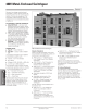
The switchgear assembly shall be Siemens
Type R and is to be located indoors, with a
NEMA 1 enclosure, (option) outdoor,
NEMA 3R per specifications below and
constructed of multiple, metal-enclosed,
ventilated sections. The front of each verti-
cal section is to contain three or four com-
partments with 14 gauge steel side sheets
and compartment barriers of 11 gauge
steel. A double thickness of 14 gauge steel
is to be provided between vertical sec-
tions. The side sheets shall be full height
and depth to provide a full metal barrier
separating the rear cable compartments
between sections. End sections shall
include provisions for main bus extension
and installation of future vertical sections.
The design shall incorporate preformed
steel channels, angles, and side sheets
bolted together and reinforced to form a
rigid, self-supporting, compact assembly.
Horizontal barriers are to be provided to form
individual circuit breaker or metering com-
partments. Circuit breaker compartments
are to be barriered from the bus compart-
ment through a primary disconnect assem-
bly. Each circuit breaker or metering com-
partment shall be provided with a hinged
front door secured with rotary latches requir-
ing no tools to operate.
Circuit breaker compartments shall include
stationary primary contact disconnects.
The primary disconnects shall be copper,
silver-plated at connection points and shall
be of one piece construction. The upper
set of disconnects shall bolt directly to the
main bus and, for feeder circuit breakers,
the lower set shall extend to the rear cable
area and shall be insulated where they
pass through the main bus compartment.
Primary disconnects shall be sized for the
maximum continuous current of the circuit
breaker which will be located in the com-
partment. Interlocks shall be provided
which will prevent a circuit breaker ele-
ment of the incorrect frame size or inter-
rupting rating from being inserted into the
compartment. A stationary circuit breaker
frame grounding contact shall be provided
which shall be visible with the circuit
breaker installed in any position.
Secondary control contacts, when
required, shall be located in the circuit
breaker compartment and shall be of the
sliding contact, silver-plated copper
design. Barriers shall be provided
between terminal points. The secondary
control contacts shall engage the
drawout circuit breaker element in the
connected and test positions.
Control circuit fuses for electrically oper-
ated circuit breakers shall be located on
the side of the circuit breaker compart-
ment and shall be contained in a dead-
front, pull-out fuse block with a clear
cover. Withdrawing the cover from the
fuse block shall automatically remove the
control circuit fuses and hold them cap-
tive. The fuse block cover shall include
provisions for being installed in the
reverse position in order to maintain the
open control circuit for testing or mainte-
nance purposes while continuing to hold
the fuses captive.
All control wiring within the assembly
shall be continuous and shall terminate
on each end at a suitable terminal block.
Control wiring shall be 14 gauge, strand-
ed, type SIS, and shall be labeled at each
end with sleeve type wire markers. Wire
markers shall be machine imprinted with
the wire name as indicated on the wiring
diagrams. Wrap on wire markers will not
be accepted. Terminals shall be insulated
locking fork or ring tongue type except
where connecting to components that do
not accept these terminations. Control
wiring for external connections shall be
terminated in the rear cable area for ease
of access. (Option) Metal covers shall be
provided over control wiring troughs
where they pass through the power
cable termination area. (Option) Metal
covers shall be provided over terminal
blocks located in the power cable termi-
nation area.
Bus
Main bus shall be three-phase, ___ wire
___ ampere copper with silver-plated
connection joints (option) aluminum with
welded connection points (option) copper
with tin-plated connection points.
(Option) Neutral bus rating shall be ___%
of the main bus current rating and shall
be located centrally in the structure for
ease of terminating cables whether
entering from above or below. 600 volt
clearances shall be maintained in all hori-
zontal and vertical buses such that insula-
tion is not required. The main horizontal
bus shall be run in a vertical, edge-to-
edge arrangement for high short circuit
strength. Access to the rear cable termi-
nation area shall be possible without
480V Metal-Enclosed Switchgear
Guide Form Specifications
Specifications


 England
  Deutschland
  France
  Italia
  Polska
  United Kingdom
  Россия
  Nederland
  España
  Magyarország
  Sverige
  România
  Portugal
  Colombia
  Suomi
Suomi  New Zealand
  Česká republika
  Türkiye
  Danmark
  日本
日本